Converting a QMX to 40-10m
On the manufacturer’s website there is a section dedicated to pointing buyers towards some nice modifications applied by other radio amateurs. One particular modification caught my eye, by Dan Koellen (AI6XG), to convert a QMX 20-10m into a 40-10m variant. That seemed like a nice project to me. Since I currently, as a novice licensee, can only use the 20m and 10m bands in the Netherlands, this would give me a third band. Pretty awesome.
Easier said than done. Try finding affordable T30-6 ferrite cores somewhere. Those things are impossible to find. Eventually, through an obscure link on AliExpress, I found a small seller who could supply them. The rest of the parts list consisted of a few SMD capacitors.
Winding and replacing ferrite cores
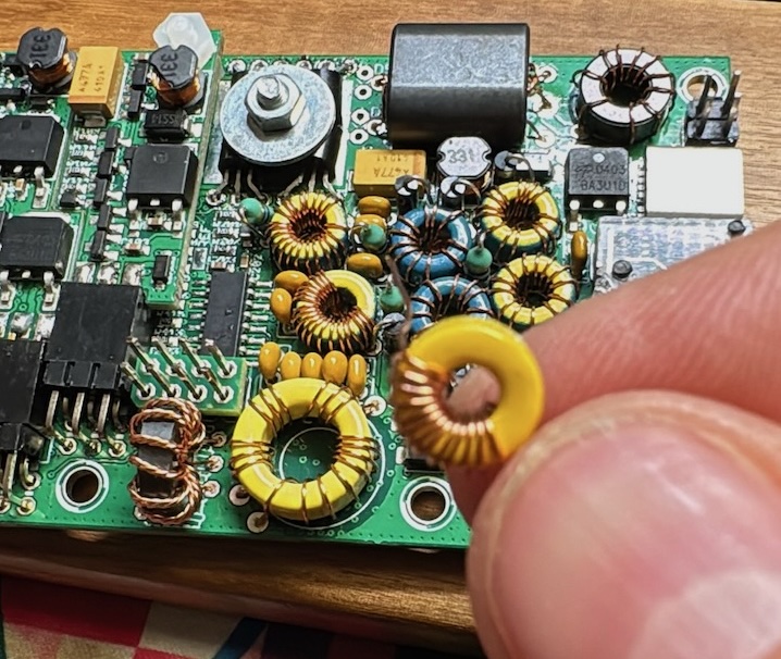
Building the new low-pass filter for 40m
This was the first challenge. I don’t have any 0.33mm wire on hand, but I do have 0.35mm wire. Perhaps that will work. According to the QMX manual itself, for the 40-60m band on a T30-6 core, about 17 turns are needed for an inductance of 1060 µH. Additionally, one with 18 turns should give me 1200 µH. After winding 17 and 18 turns I connected the LC meter — also AliExpress quality of course — and the results were disappointing. Way too low. Time to add more turns then. After 4 extra turns per core I reached the desired values, everything seemed fine so far. (Unfortunately, as it turned out later…)
Now it’s time to desolder the old LPF0 cores. This is a tricky job because the QMX PCB is 6 layers thick, meaning it requires a lot of heat to melt the solder. Under a magnifying glass this is a manageable task. Then comes the obligatory fumbling with a desoldering pump, which I always struggle with. The PCB is quite thick with its 6 layers, so quite a bit of heat is needed to get everything liquid through all 6 layers. After some impatient handling of this pump, I managed to get 4 acceptable holes that are just large enough to push the 0.35mm wire through.
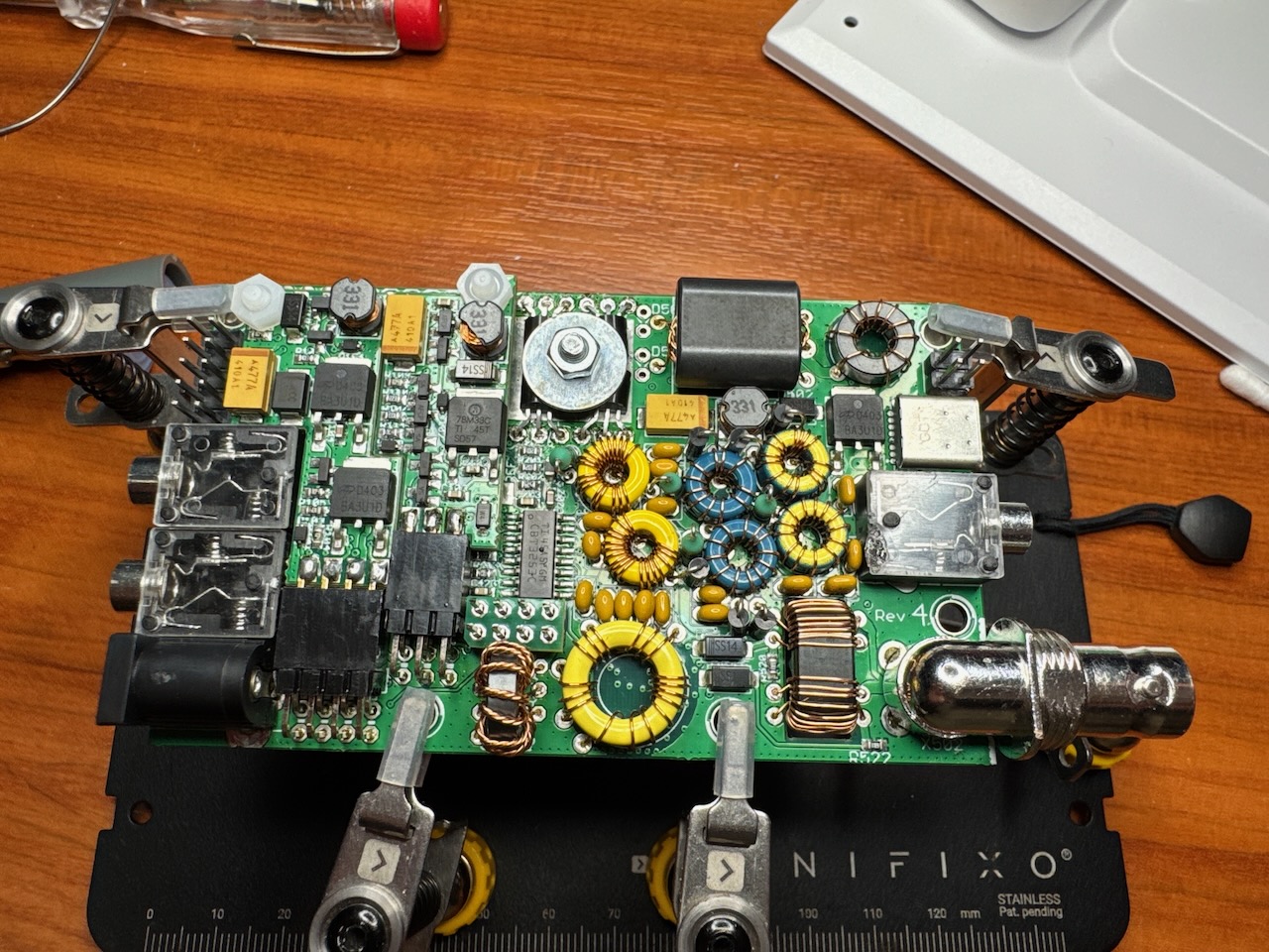
LPF0 replaced
I didn’t immediately throw away the old LPF0 cores for the 20m band. Just to be safe, I measured them with the LC meter. These cores worked fine — could it be that the LC meter is unreliable? After many recalibrations and measurements, it became clear that cheap-is-expensive is the fate of this LC meter. It’s an unreliable thing. Where I should have seen ±706µH and ±640µH, I got varying numbers between 517-570µH, with the core having fewer turns sometimes measuring more µH. Let’s set this meter aside and trust the knowledge of the QMX designer.
| Number | Value |
|---|---|
| C514 | 270 pF |
| C517 | 560 pF |
| C520 | 33 pF |
| C523 | 270 pF |
| C402 | 100 pF |
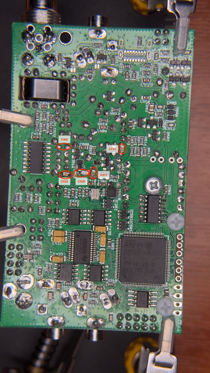
SMD capacitors in the correct position with proper numbering
Once the cores are in place, it’s time for the SMD capacitors. This is where the trouble begins! AI6XG’s blog post shows a nice photo with extra soldered SMD capacitors. But they are all unnumbered items. How am I supposed to figure out which values go where? There is a nice table with values for the SMD capacitors and ferrite cores. But try guessing which capacitor value needs to be soldered at each position. I had to puzzle over it a couple of times before it clicked. After opening the QMX version 4 manual, I found the technical schematics on numbered pages 16 and 17, where I found reference points that allowed me to decipher the solder points for C514, C517, C520 and C523. For those, like me, who are illiterate in electronics — the correct positions are indicated in the photo. C402 is empty, why is that? The story will tell later…
Armed with tweezers and a fine-tipped soldering iron, this remains a job that requires more patience than I can muster. But with much blood, sweat and teeeears, I muttered: “I am never doing this again…”. With components of just 1.5mm, this remains a job to curse at.
After letting everything cool down, the work is inspected under the magnifier. Photos are also taken and enlarged further to examine from different angles. You want to make sure all contact points are good. Especially with the combination of C520 and C517, you need to be careful not to solder everything together.
The disillusion!
After the inspections, it’s time to carefully connect the device to power. This QMX is built for 12 volts, but it’s wise to carefully start at 7.5V with a maximum of 250mA. This setting is sufficient to start up the QMX, but not to transmit. The power source is an adjustable supply, and it’s important not to switch on the QMX immediately. First, check that there is no leakage current. If leakage current is detected, you need to redo the inspections and repair everything. Fortunately, this turned out not to be the case, so the device can be powered on. Everything starts up fine.
Time for the next step. Connected properly to 12V and with the USB cable to the laptop. Once on the MacBook, I open the terminal and type the commands to connect to the QMX.
# stty -ixon -ixonff
# screen /dev/cu.usbmodem6
The stty command is needed to make the key combination CTRL-Q work in a macOS terminal.
The screen command opens the connection to the correct serial port.
Once in the settings, I adjust the band configuration; 11m out and 40m in. While running the RF sweep to validate the Band Pass Filter(s), the results are disappointing. The values I measure for 40m don’t match the website. The values are on average -10 to -20dB below those in the manual. Even after repeated tests. Below are the RF sweeps on 40, 20 and 17 meters on the original BPF3 and BPF2 as built in the 20-10m kit.
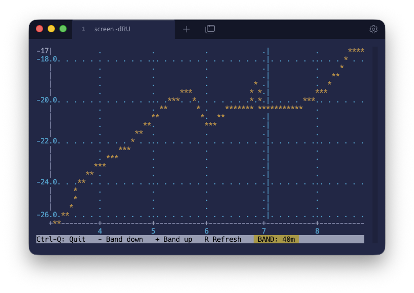
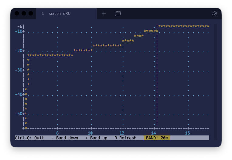
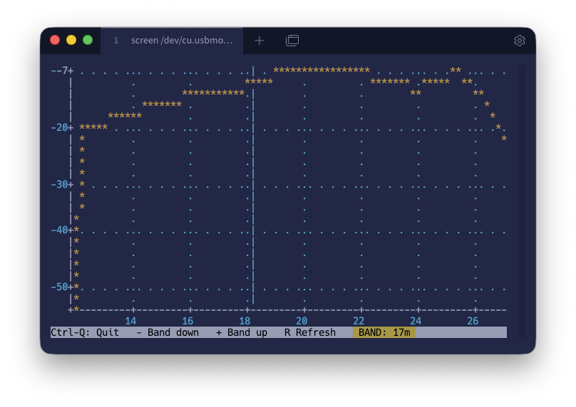
The mistake was quickly found. Reading the blog again, the clue was there. The provided table and photo of the PCB only show the components for LPF0. Later in the article, there is mention of modifying BPF3, but this modification is nowhere indicated in the PCB photo nor in the original table. This is the previously mentioned ‘C402’ component that is listed in my table and shown on the PCB photo.
This is where things get exciting!
After modifying C402 with an extra capacitor, the RF sweep values match AI6XG’s values to within a few dB. The performance of the 40m band has improved enormously from approximately -22dB to -11dB. This turns out to be the correct modification for the QMX. So far, operation successful and the patient is still alive!
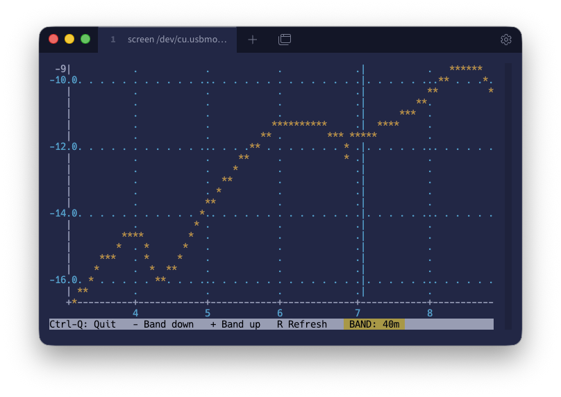
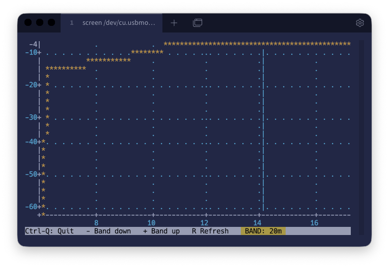
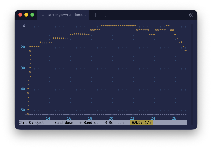
| Band | BPF3 original | BPF3 modified |
|---|---|---|
| 40m | -22dB | -11dB |
| 20m | -6dB | -4dB |
| 17m | -8dB | -7dB |
And now in practice…
Bench testing on a computer terminal with RF meters is fun of course, but does it actually work in practice? Time to put the rig to the test. First, carefully testing with a dummy load and seeing what the WebSDR thinks of it. Even though you’re transmitting into a dummy load, something always radiates. Enough to receive at home on the WebSDR.
The delivered power according to the internal SWR/Power meter:
| Band | Power |
|---|---|
| 40m | 4.3 W |