QRP-Labs QMX Build
We are starting a few days before the exam date for the novice radio amateur exam. Somewhere I still don’t feel completely confident about passing the exam, but I really want to get a radio fairly quickly. If I pass the exam on the first try, I can get started right away.
At the club I had already been in contact with fellow amateur PA1HJT, who had gone for a uSDX device as his first radio. That seemed fun to me as well, but after watching a few YouTube videos I started to doubt again. After watching some more YouTube, I ended up with a device called the QMX from QRP-Labs. A one-man company run by a Brit living in Turkey.
In the webshop, a fully built QMX with a nice metal case can be ordered straight away. I chose the 20-17-15-12-11-10 m band variant. This gives me access to five bands for transmitting and receiving, and the 11 m band for receiving only. The ordering process is quite easy and quick. You have to tick a checkbox confirming that you understand there is a queue, which appears to be fully updated up to yesterday. So, click, and the order goes through.
What have I done!?
Just one day after placing the order, panic sets in. Out of curiosity I visit the website again and read everything more carefully. Am I reading this correctly? What have I done?! After going through the website once more, it turns out that the online list with order numbers and dates does not show how far production has progressed, but instead represents the production queue. A quick calculation teaches me that it will take more than four months before the radio arrives at my home! For a beginner amateur, that’s obviously not a pleasant prospect.
With a sinking feeling, knowing that the mistake is entirely mine, I send an email to the QRP-Labs support team. A short email exchange with Hans Summers himself, the designer and engineer of these devices, results in the order being changed from a fully built unit to a kit, which is quickly confirmed by email.
About two weeks later, the mailman rings the doorbell with the QMX package in hand. Of course, the box is opened immediately at the workbench, and I begin to realize what I’ve gotten myself into. Only when one sees the entire kit laid out in full, one realises just how small everything is. How am I ever going to put this together?
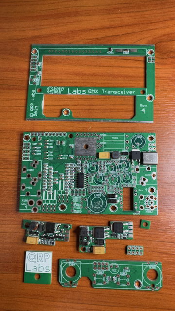
The QMX comes with a very good manual. It is not included on paper, but must be downloaded from the QRP-Labs website. Rarely have I seen such a good and detailed manual. It guides you step by step through assembling the QMX+. Having a magnifying glass or a desk magnifier with lighting is absolutely essential. Some components are extremely small and come in multiple values in identical, indistinguishable packaging. Ceramic capacitors are a good example. In that case, it’s very helpful to be able to read the identification markings with a magnifier.
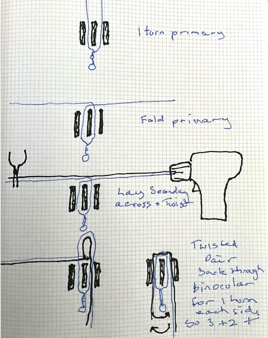
Really weird twisted sister pair from the manual
The build itself progresses surprisingly quickly. Thanks to the clear explanations in the manual, and by literally following what the author suggests, everything goes smoothly. The first definitive choice that must be made during the build comes up quickly: the power transformer. You have to choose whether to configure the device for 9 V or 12 V power sources. I choose the 12 V variant. Reading through the documentation, it turns out that in earlier versions of the QMX, QRM was caused on the 10 m band by the power transformer. Because of this, a special method must be used when building the “twisted pair” for winding the transformer core. Below is an image from the manual, which I will not attempt to reproduce. It’s great to see how a hand-drawn sketch ends up in a digital PDF to explain the construction.
I had no previous experience with making bifilar wire, so this was my first challenge. Thanks to the manual above, it was perfectly doable.
Power transformer for 12 V.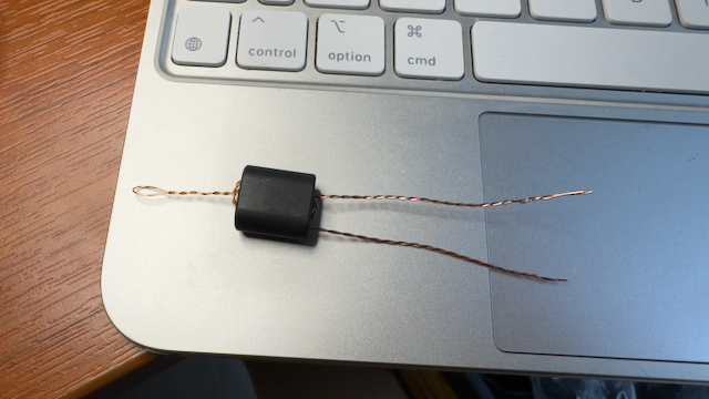
Slowly but surely, all the components begin to come together. Building the low-pass filters is still a bit of delicate work, as the toroids are extremely small, but with a little patience it is perfectly manageable. According to the manual, it is not only the number of turns on the toroids that matters, but also the spacing between those turns. This spacing has a surprisingly large impact on the output power.
The effect appears to be most pronounced on the lower row of LPF toroids. Tests show that if the left-hand LPF is wound perfectly neatly in a circular pattern with equal spacing, the output power drops from 5 W to around 3 W. On a QRP radio, being able to transmit those extra watts is certainly something you do not want to give up. So they have to be tighly grouped together until they cover only 50% of the toroid.
Low pass filters voor 20m (left), 17-15m(centre), 12-11-10m (right)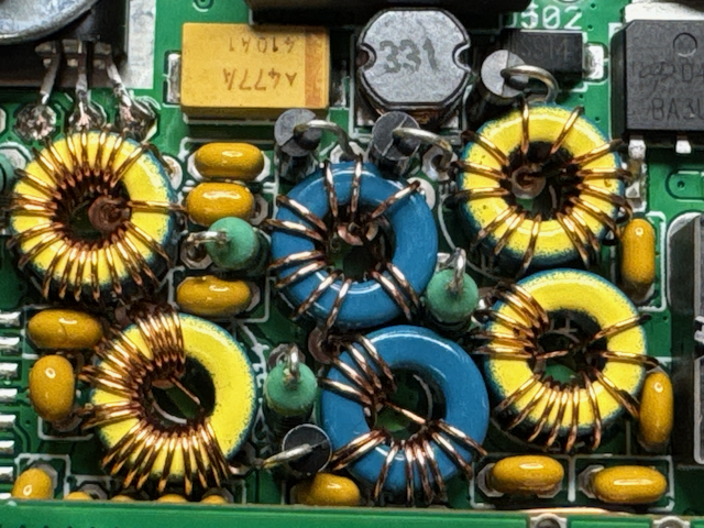
Trifilair on a toroid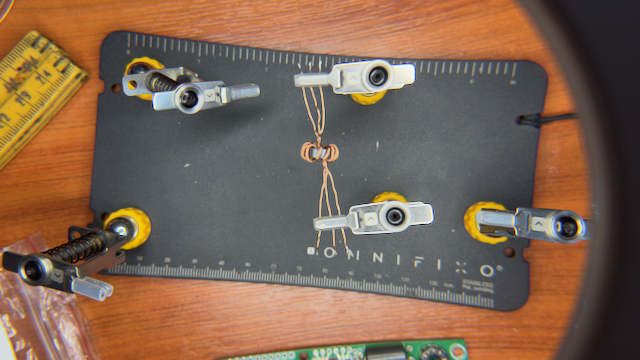
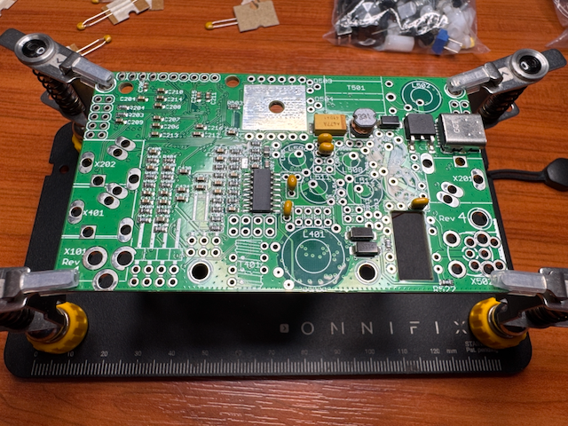
Main QMX tranceiver board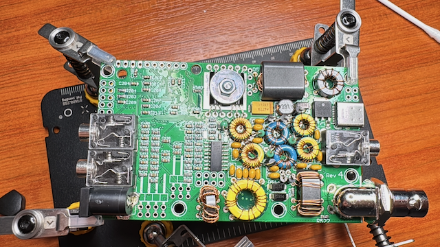
Next came installing the buck converters, knobs, and display — about an hour of soldering in total. The display took the longest, with sixteen connections that each had to be soldered to leftover pins from previous components — a clever way to reuse scrap.
Knobs and first buck converter installed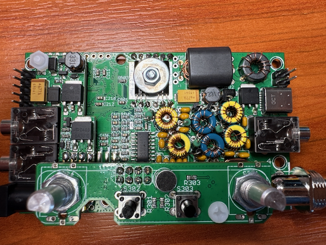
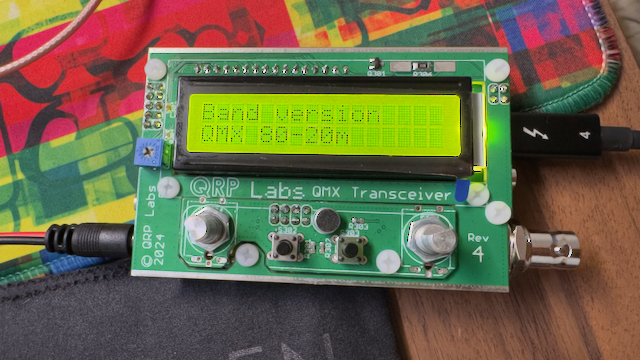
With everything in place, the QMX could finally be assembled. It was a tight fit, as the display PCB must slide over the button PCB, leaving less than a millimetre on either side. After multiple checks with a multimeter to ensure no shorts — also detailed in the manual — I powered it up carefully, starting at 7V and 500mA to avoid frying anything if there were any hidden shorts.
To my amazement, it worked perfectly. The device powered on immediately and prompted me to select the bands. I had to switch from 80–20m to 20–10m, after which it ran its internal checks.
First start of the QMX