Z-Match QRP Tuner With a Twist.
Within our club, more activity is emerging. One of the new projects will a 4-week evening course for the NanoVNA given by PA1HJT, where yours truly may also provide some assistance. Some people only use the VNA as a glorified SWR meter, but this little Swiss Army knife of a device can do much more. But that’s reading material for a later time.
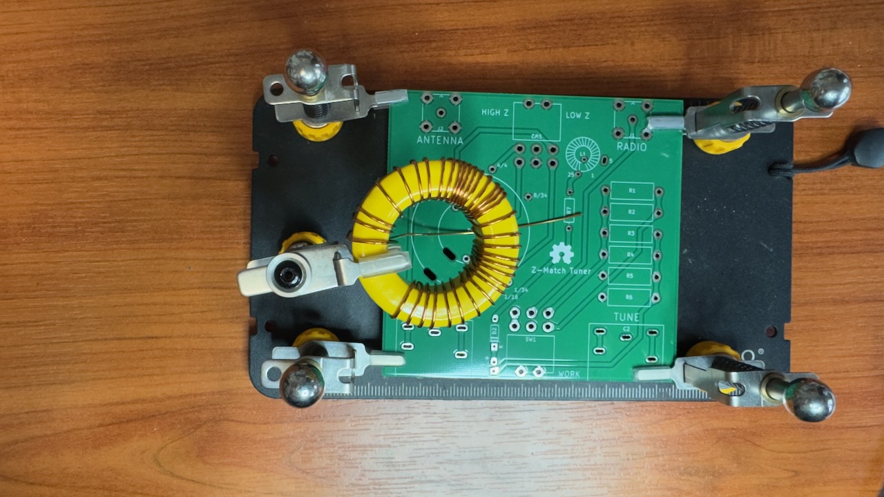
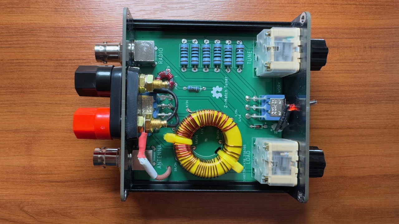
For me, this was actually the reason to start on the Z-Match QRP Tuner. This little device, available from many sellers on AliExpress for a reasonable price of around €30, is going to help me with the NanoVNA project, but also in the field during QRP activations. The Z-match is a manually operated tuner. This means that with a small turn of the knob you can easily visualise when an antenna setup is capacitive or inductive. Connected to a NanoVNA, you can clearly see the effect on an antenna setup.
The kit delivery is fairly bare-bones. A proper electrical schematic is included, but a complete manual for the assembly order is almost entirely absent. Almost is the key detail here, because only for the large L2 coil is it explained how it should be wound.
L2 coil with the first wire
We start the build with the largest component first. This needs to be assembled with care, so I’ll leave soldering all other components until this one is done; The L2 coil. Things quickly get confusing. In the drawing, the winding goes counter-clockwise, entering from below and exiting from above. But when I look at the hole placement on the PCB, it needs to be wound the other way around. Still counter-clockwise, but entering from above and exiting from below. No sooner said than done, 34 turns are wound on in no time.
After this, 16 turns of the next piece of enamelled copper wire need to go in the same direction. No sooner said than done, but then comes the challenge. Now I see four more turns, but these go in the opposite direction. After some searching online and watching a few videos, I figure out that this is indeed correct. The fact that this third wire doesn’t sit perfectly straight between the other two bothers me enormously, but I decide to ignore it.
Next comes the precise counting and careful work with a sharp blade. At turn number 8 and turn number 16, the enamel needs to be scraped off. A tapping point needs to be soldered here. In this case, they didn’t want to use a loop or two separate wires. So this solution was chosen. It works fine, so why not.
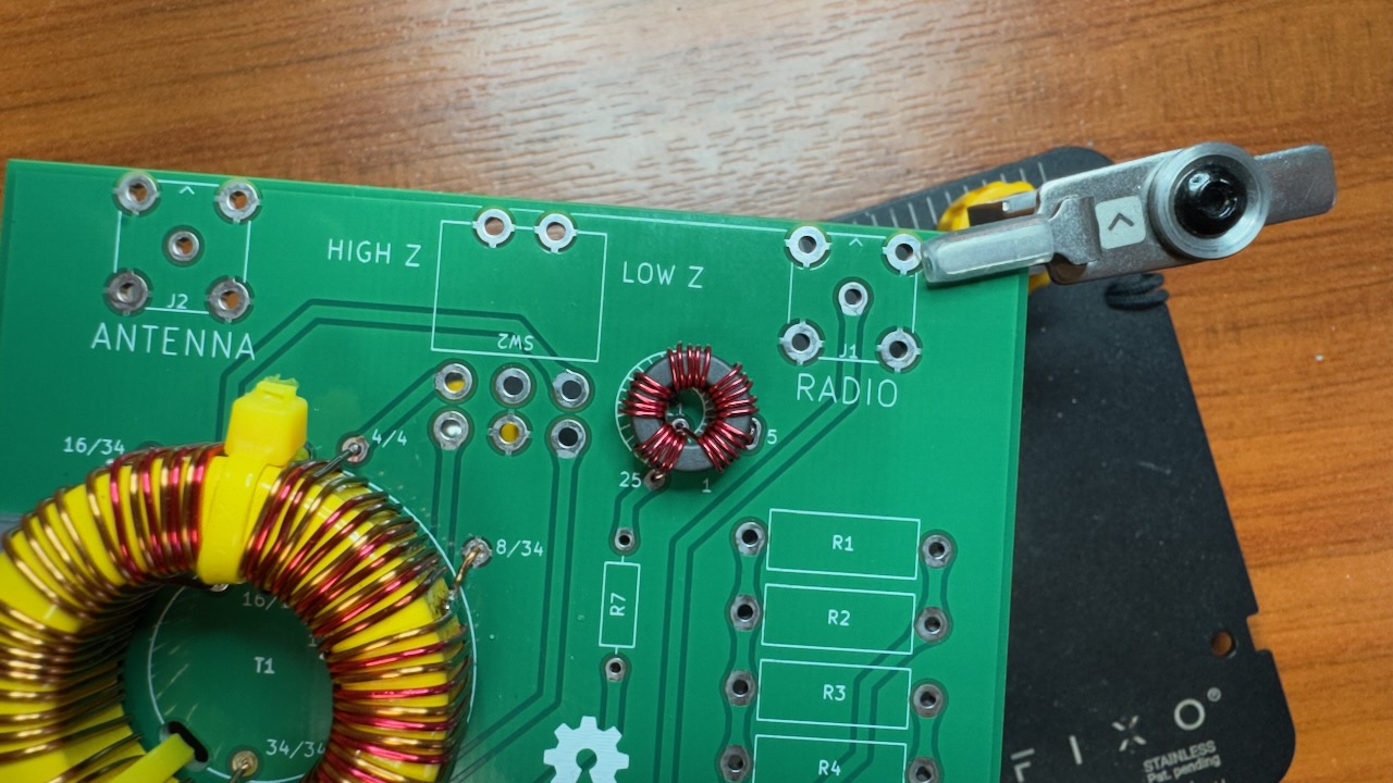
The L1 and L2 coils together
Winding the L1 coil was also a mystery at first, until I looked at the PCB more carefully. It was clearly described there. From point 1, 5 turns need to be made. There’s a wider hole there, so that must be a loop. Then keep winding until you have 25 turns, and the end needs to be soldered into the PCB there.
What follows is a standard small puzzle to solder all the simple components in their places. Do pay attention with the BNC connectors to keep everything straight. The variable capacitors require some loose ends to be clipped, but it doesn’t get more exciting than that. While soldering, I already found time to drill a hole and poke some coax through. This is not part of a standard Z-match tuner. Here comes the twist.
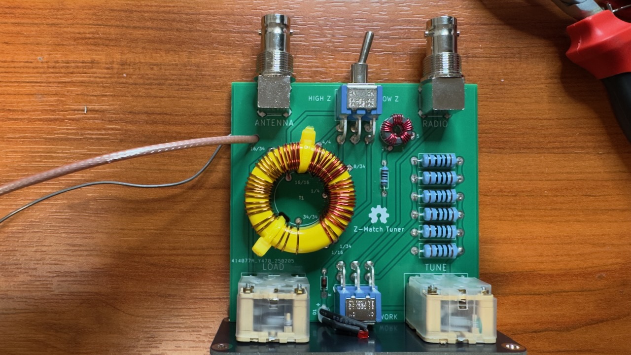
The base is done…
The (un)balanced line modification
(un)balanced line modification
I wanted to add an extra antenna option to the Z-match tuner. In its current form, it’s made for BNC connectors only, but in the original design of the manual tuner, it’s also capable of working as an (un)balanced line tuner. I discovered this through a video by LY2H, a Lithuanian YouTuber who explains this in great detail. The basic principle is simple. One port needs to be soldered to the core of the antenna port, the other needs to go through a switch to connect to a winding in the circuit to hook it up correctly.
To make this possible, I drilled a 3.5mm hole in the PCB at a spot where I knew no important traces run, and I ran RG316 through it connected to the red banana plug. Additionally, I connected the black banana plug with an extra switch to toggle between balanced and unbalanced line. a small modification that greatly broadens what the Z-match tuner can do.
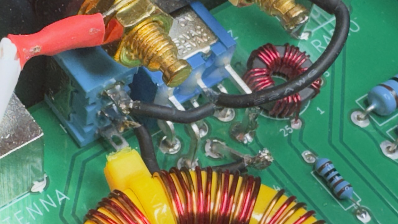
Switch detail between balanced and unbalanced
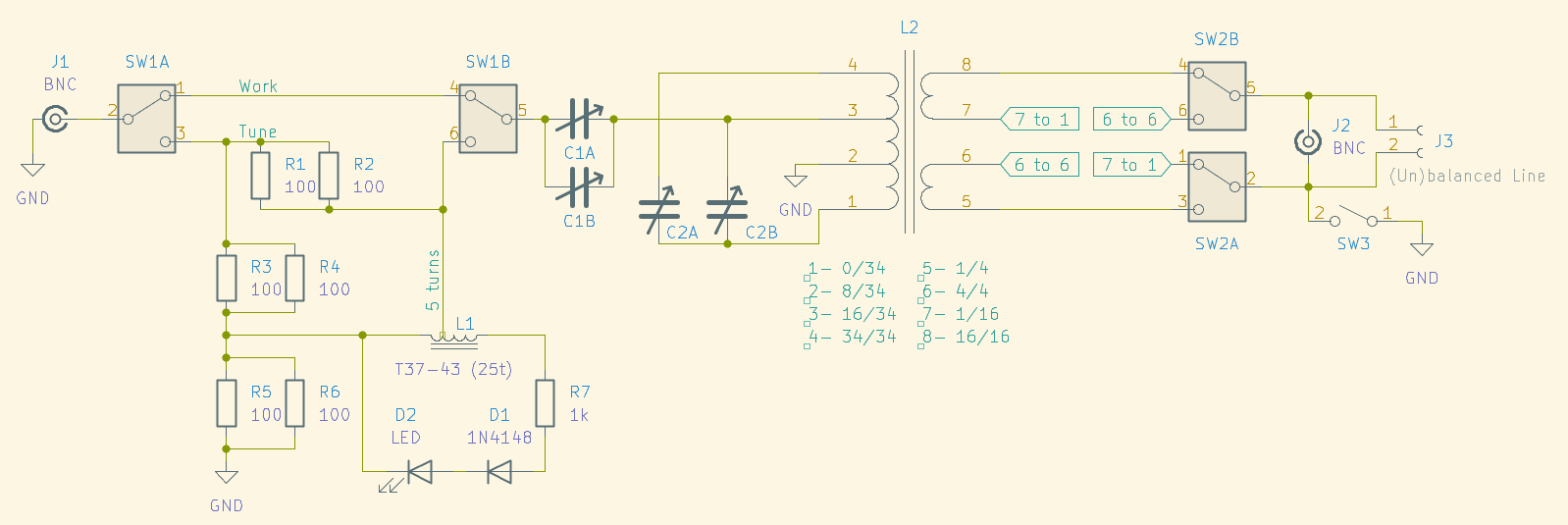
Lastly, the modifications to the Z-match schematic:
Z-match QRP schematic