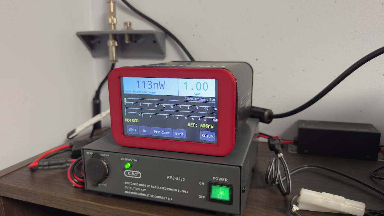
LJ2000M SWR Power Meter
A good SWR and power meter is an important tool for any radio amateur. Unlike the SWR meter built into my radios, the ICOM IC-705 and IC-7300, I didn’t actually have a proper standalone meter that could measure SWR well. Sure, I could have just gone to a webshop and bought a commercial option, but building one yourself is way more fun! For me, DIY always comes with a hefty dose of trial and error — but that’s exactly where the learning happens. On top of that, I wanted a nice digital meter that could do more than just measure SWR.
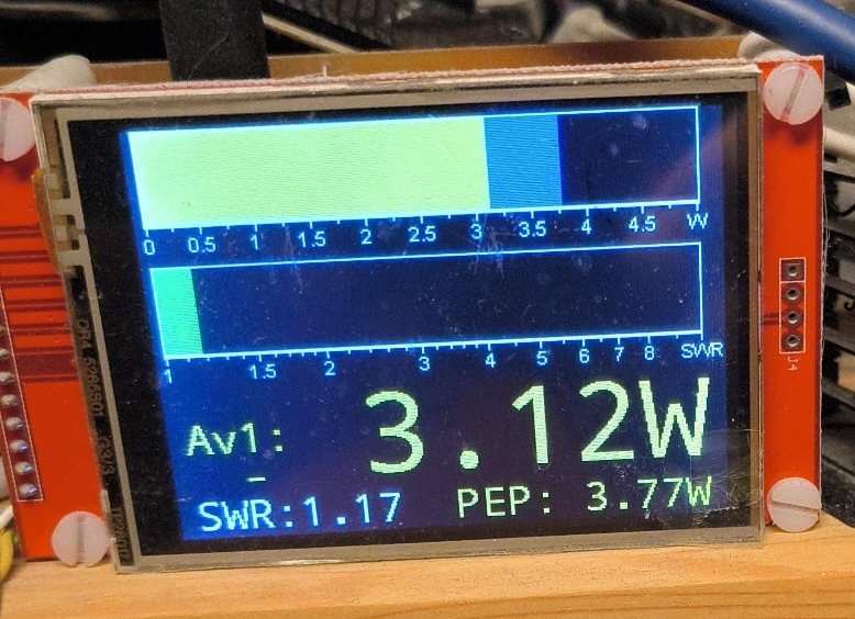
PD0PHA’s meter
Fortunately, I didn’t have to look far for a brilliant tip. Radio (and Volvo) friend Peter, PD0PHA, pointed me toward a great project by Loftur Jónasson, TF3LJ. Peter had built an early version of this project himself, back when it was still very much an active project. I couldn’t resist going through a whole series of photos of his build with a hand-made PCB. The interface was maybe a bit dated, but it was supposed to be a meter with an extreme range, capable of measuring anything from milliwatts up to kilowatts. I thought that was fantastic. I want one too!
PD0PHA’s meter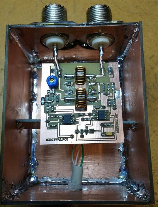
The project was originally more than 10 years old, and around June 2020 things went quiet on Loftur’s page. Uh-oh, do I really want to get into this?! But after some digging it turned out to be anything but dusty: it’s since been picked up by Johan Holstein, PD0LEW, and turns out to be very much alive as an active open source project. A nice example of how knowledge in our hobby keeps living on — passed from one builder to the next.
The LJ2000M project
This is an open source SWR and power meter project with a Teensy 4 at its heart. It started life as Loftur Jónasson’s “Tiny Power and SWR Meter” and has been considerably developed further since. Johan took over that development and keeps the project alive on his Groups.io page RadioStuff., together with Paul Davis, K9MR, who has contributed a lot to the new interface.
Technically, the meter measures power via two AD8307 logarithmic amplifiers, with an AD7991 A/D converter digitizing the analog outputs, which are then read by the Teensy 4. For the display, a nice large 5" TFT touchscreen was chosen. In a more recent development, an ESP32-C3 has even been added, which can show the readings via WiFi on a webpage, straight on your computer.
Features of the LJ-2000M:
- Measures both SWR and transmitted power
- Very wide measurement range (µW to kW), depending on the coupler used
- Touchscreen display, available in 5" and 7" variants (RA8875-based)
- Supports multiple measurement bridges at once via a dual-CPU coupler setup
- Supports network access via a built-in webserver (WiFi webpage)
- Fully open source: hardware, firmware and documentation all freely available
Building it
SMD components, HELP!
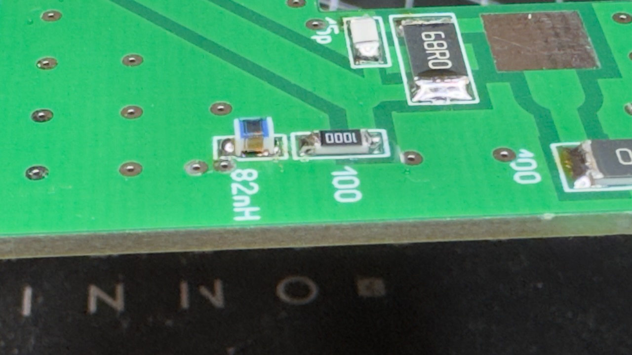
When SMD components come up, alarm bells start ringing for a lot of amateurs. There’s a common feeling that it’s too fiddly, way too small, and just not doable. That’s often true — but in this case, the component sizes were chosen with that concern in mind. Johan redesigned the boards so that SMD soldering is achievable even for the less experienced amateur. Instead of tiny SMDs like 0402 or 0603, almost everything is designed around 1206 or 2512.
To put it in perspective: think of 0402 as grains of sand, and 2512, at the other end of the spectrum, as decent-sized paving stones. Most components are 1206 size — roughly the size of a regular through-hole resistor, just in SMD form. Perfectly doable, even for an untrained pair of hands like mine.
| Type | Length | Width |
|---|---|---|
| 0402 | 1.0mm | 0.5mm |
| 0603 | 1.6mm | 0.8mm |
| 0805 | 2.0mm | 1.25mm |
| 1206 | 3.2mm | 1.6mm |
| 2512 | 6.3mm | 3.2mm |
Only for the tiniest ICs, like the AD7991 and the PE4259-63, did I need outside help. Luckily PA3COR, a fellow amateur from our tinkering group, had the right gear to tackle that miniature stuff.
Dual CPU Coupler — the heart of the system
Soldering a board like this doesn’t make for the most thrilling story, of course. Most of you are used to steadily building up a board from low to high components, to avoid getting stuck with the soldering iron. So here’s a small collection of photos showing the board coming together step by step.
Dual CPU Coupler 1 of 4 Dual CPU Coupler 2 of 4 Dual CPU Coupler 3 of 4 Dual CPU Coupler 4 of 4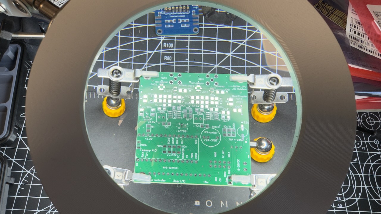
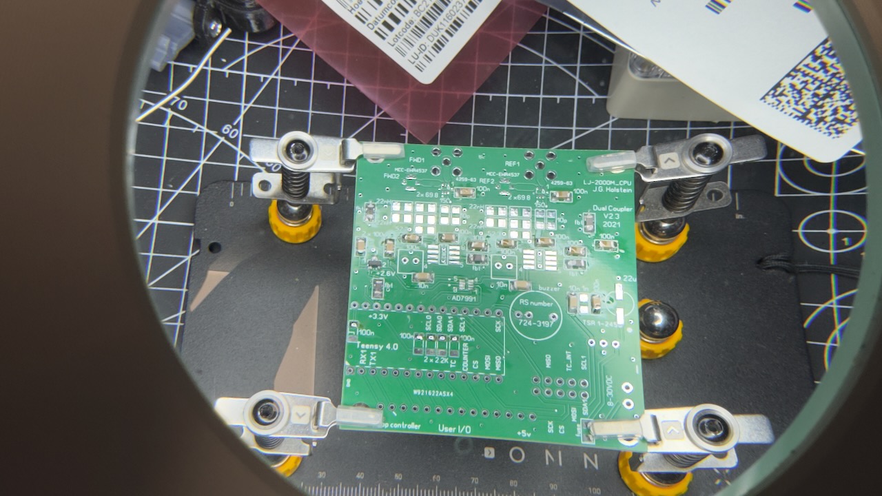
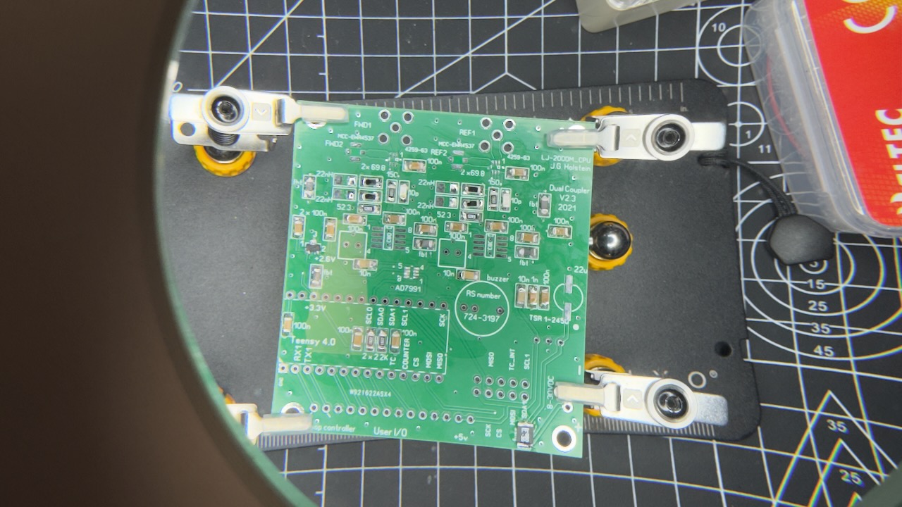
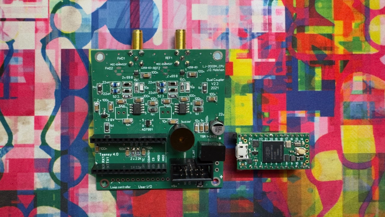
Sharp-eyed readers will notice the U.FL/IPX mounts for the second measurement bridge input aren’t soldered on yet. They simply hadn’t arrived yet at the time of writing.
HF Coupler — the measurement bridge
Building the HF coupler follows much the same process as above. Part of the soldering work also involves fitting it into an aluminum enclosure. So, a few more photos below.
HF Coupler build 1 of 3 HF Coupler build 2 of 3 HF Coupler build 3 of 3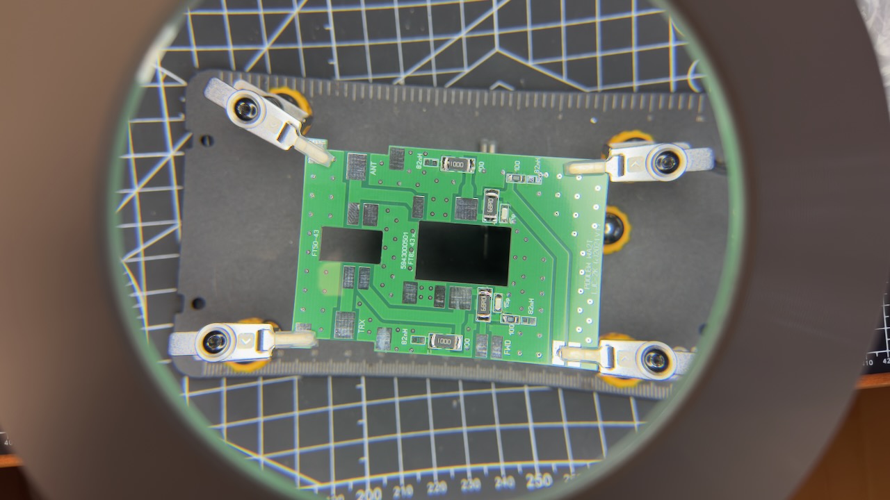
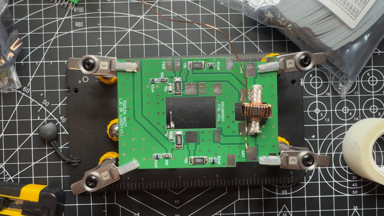
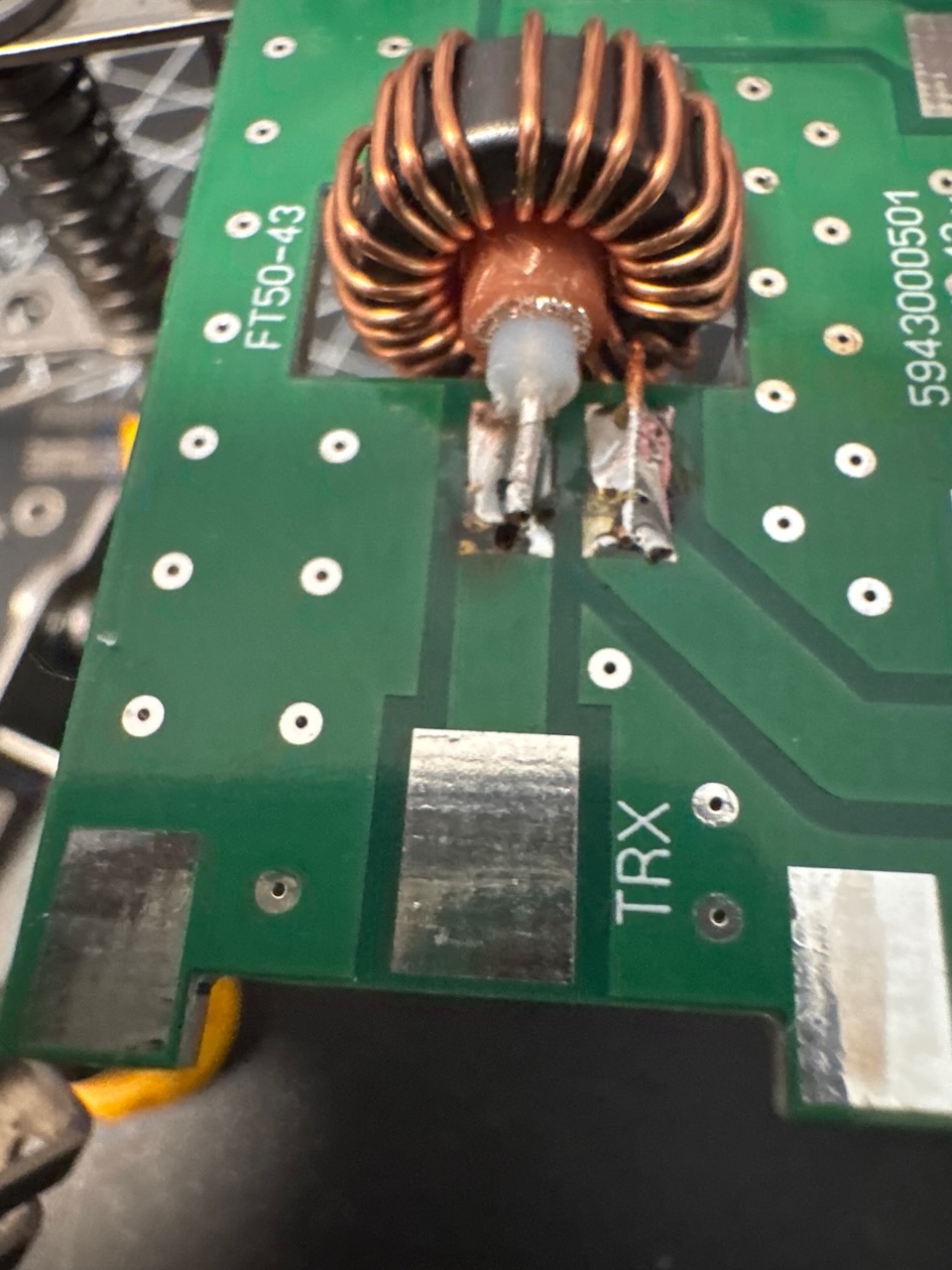
The first question this raised for me — and probably for the curious reader too — is: why not just run a wire straight through the wound cores, why coax? What’s happening here is that we’re trying to prevent capacitive coupling between the windings around the ferrite core and the wire running through the core. We do that by using the coax shield as a screen, and connecting it to ground on the antenna side. Any capacitive coupling is then immediately drained off, so it has no effect on the wire we’re actually measuring across.
Below are some more detailed photos showing the coax shield connected to the PCB ground.
HF Coupler coax detail 1 of 4 HF Coupler coax detail 2 of 4 HF Coupler coax detail 3 of 4 HF Coupler coax detail 4 of 4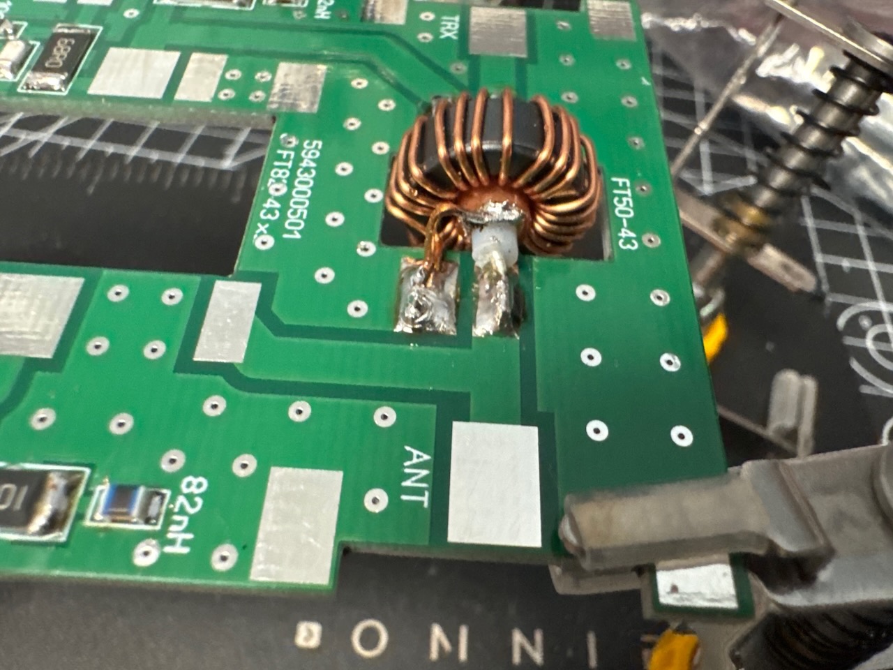
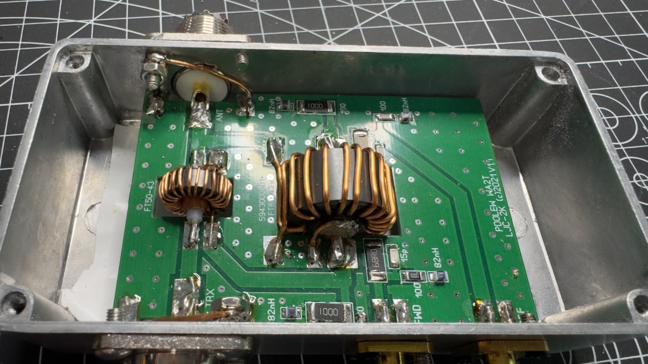
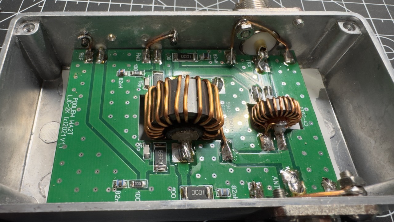
Here’s the final result after building it. Neatly tucked away in an aluminum enclosure.
Finished HF Coupler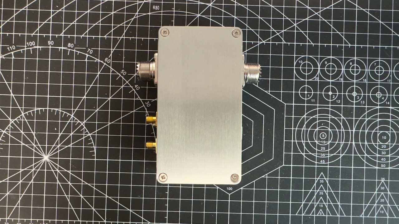
Hooking everything up and testing
With everything finally soldered, it was time for the small PCB that connects the screen to the CPU Coupler. A fairly simple job, routing 9 pins from the CPU Coupler to the screen. Not many detail photos of this one, other than a few I took in passing while troubleshooting.
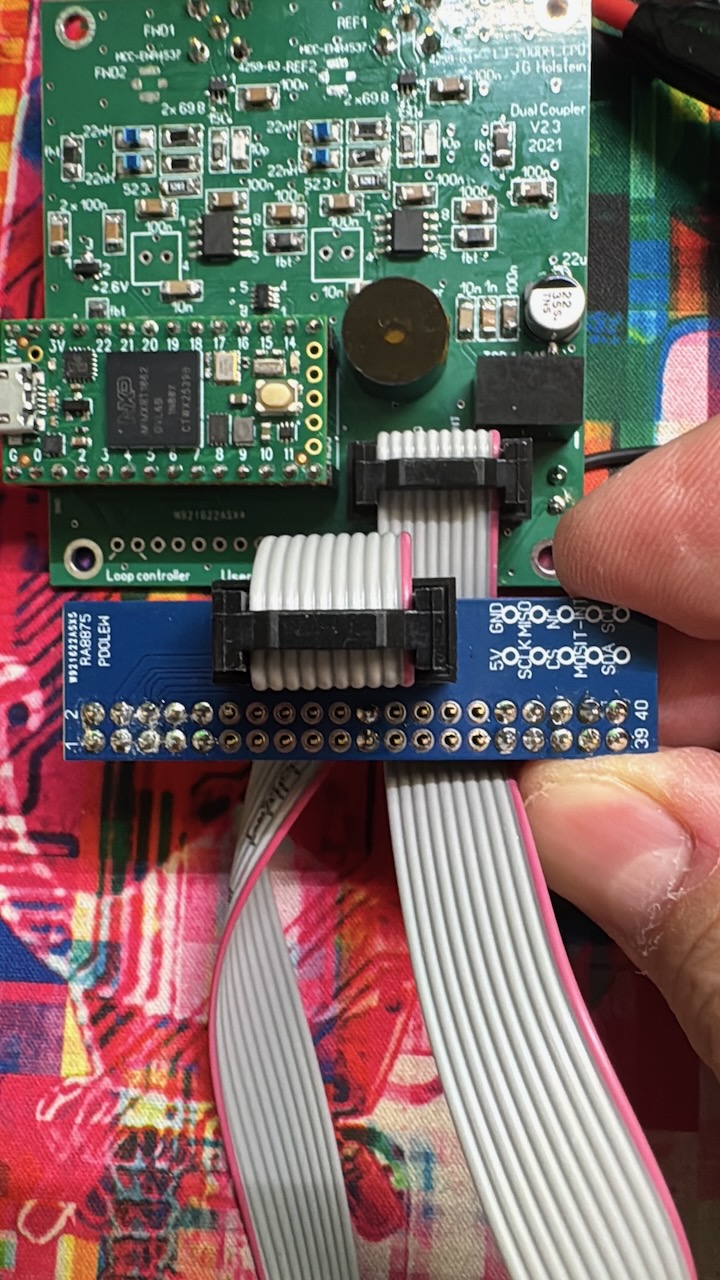
Screen PCB
After hooking everything up, there was unfortunately a temporary letdown. The device powers on, the screen lights up. I see the boot screen, the initialization screen for the AD7991 and GSL1680, and then the screen goes black. During the project I was in touch with Johan a number of times, and he was hugely helpful in getting the whole thing working. Once I had the correct screen connected, it still wasn’t behaving quite right. After a video call and stepping through the whole system with diagnostic firmware, everything seemed fine — but it just wouldn’t work. So the whole unit went in the post to Johan. Something had to be wrong in my build, something I wasn’t going to figure out on my own. After more testing and different firmware versions, it turned out the AD7991 itself was faulty. Johan replaced it with a new one, and then the system worked. Still very much thank you for that, Johan!
Once I had the unit back home, I hooked everything up again straight away and… “hooray!” it works.
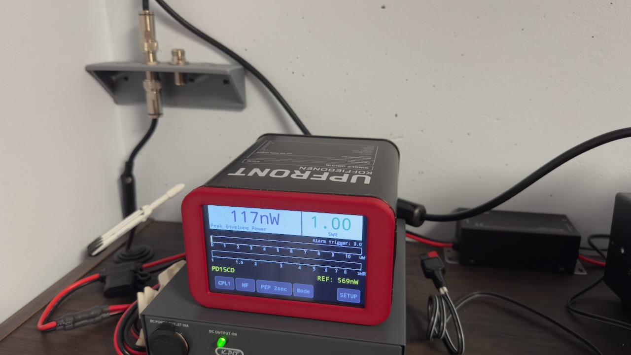
After this whole adventure, I built the whole thing into an old coffee bean tin. Going with the “use what you already have” philosophy, I still had an empty coffee tin lying around. The Dutch company Upfront sells all kinds of sports nutrition products, but also leans heavily into “clean” and “honest” food. As it happens, they also sell coffee at very reasonable prices: for about €9 you get 450 grams of beans in a sheet-metal tin. Gorgeous, and almost perfectly sized to fit the screen.
I designed and 3D-printed my own front panel to go around it.
The coffee tin Almost a perfect fit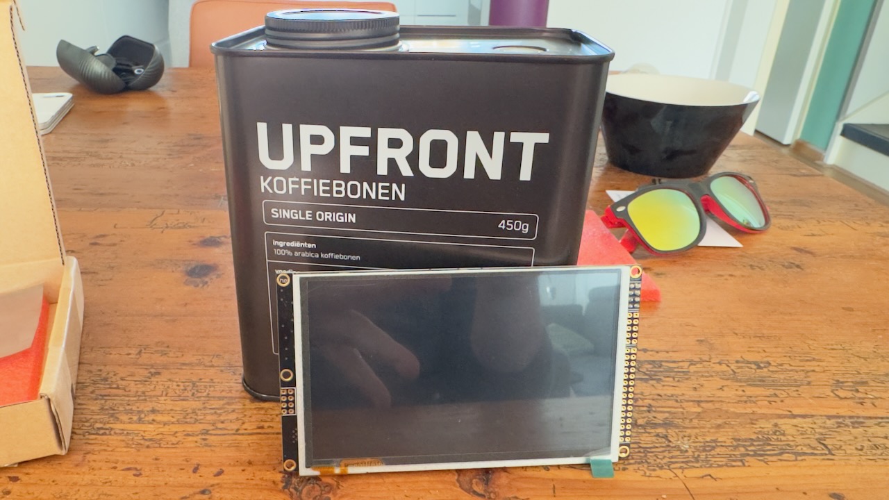
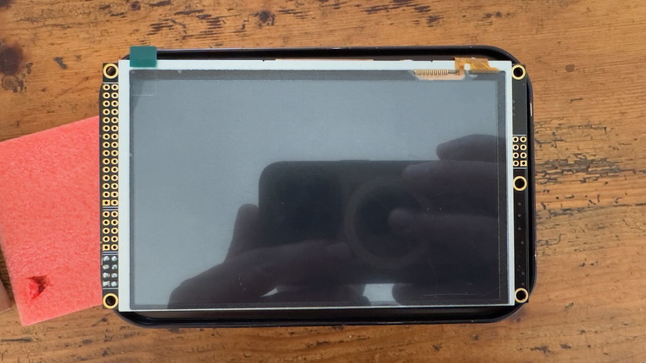
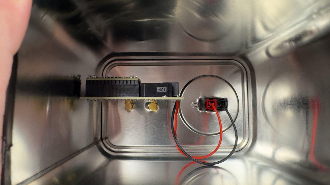
Then I cut all the necessary holes and wired everything up inside the tin:
Back of the coffee tin with connectors Inside view of the tin Everything finished in the tin and powered on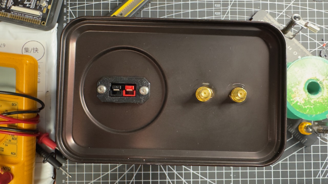
Calibration
Once everything was working and nicely built in, it was time to calibrate the unit. Note: connect the antenna output of the measurement bridge to a dummy load — ideally one that can dissipate at least 100 watts.
Calibrating Forward (FWD)
Once everything is connected, calibration can begin. Press the SETUP button, then go to the CALIBRATE button in that menu. For an accurate calibration, go with the two-step calibration, starting with 1ST LEVEL CAL. In the menu that appears, set the dBm value you want to calibrate at — for example 40 dBm (10 watts) or 60 dBm (100 watts). Make sure the two calibration points are far enough apart, so you calibrate across as wide a range as possible. The recommendation is to calibrate the 1ST LEVEL at 100 watts and the 2ND LEVEL at 10 watts.
You’ll first see POOR SIGNAL QUALITY in red on the screen — that’s simply because you’re not transmitting yet. Put your radio into FM mode so you get a carrier. Do not calibrate in SSB mode!!
Press the PTT button. If “Reverse signal detected” appears on screen, the SMA cables are connected the wrong way round. Swap them and press PTT again. If all goes well, it’ll show in green that the signal has been detected, and you can press SAVE to store the calibration. Then press BACK and select 2ND LEVEL CAL. Repeat the same steps with the PTT button and save this calibration with SAVE as well.
Calibrating Reflected (REF)
This is essentially the same process. Except this time you deliberately need to have the SMA cables swapped to calibrate the reflected side. In other words, follow the steps above, but make sure you see “Reverse Signal Detected” on your screen.
Installing the ESP32 webserver
Activating the webserver requires a small extra PCB. It takes the Teensy’s original spot, and the Teensy and the ESP32-C3 are then mounted on this board.
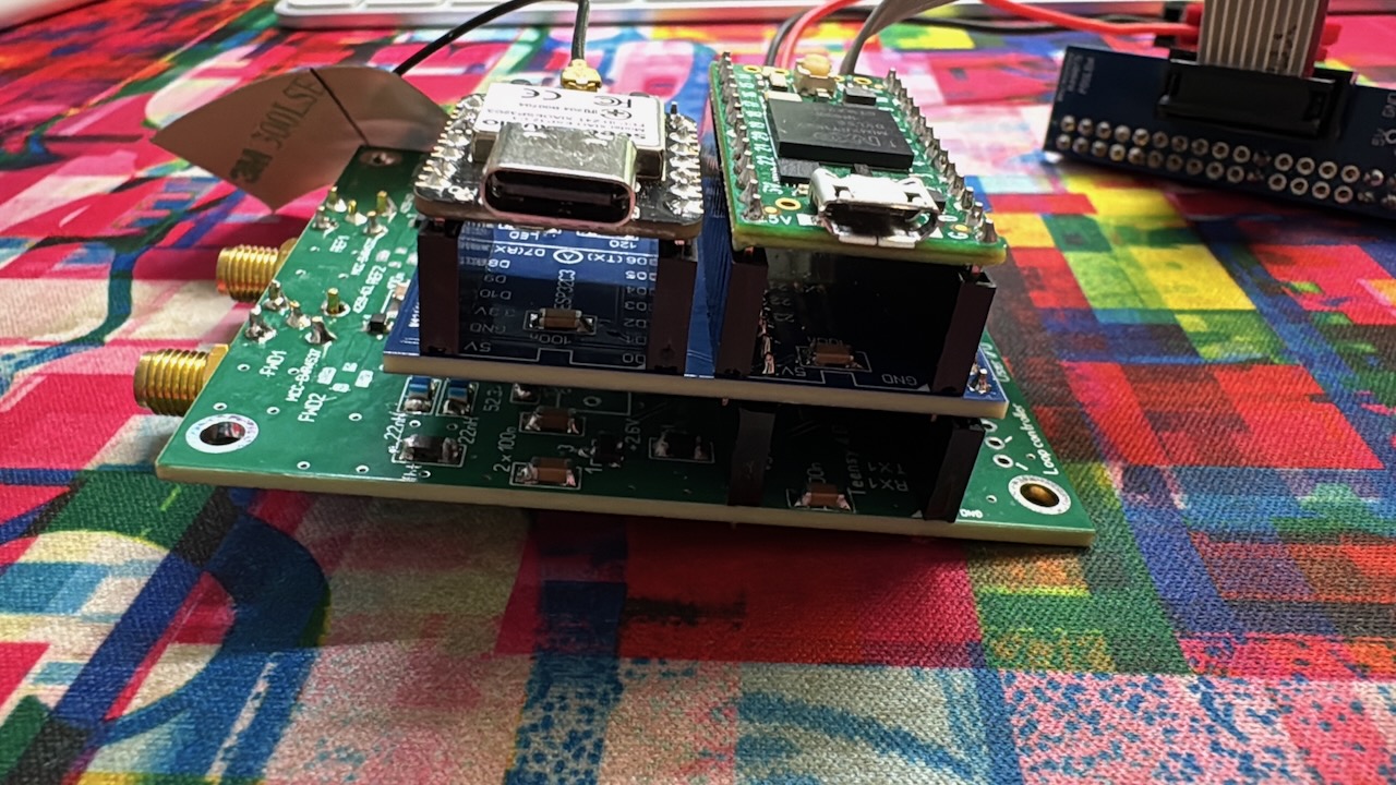
CPU Coupler board with webserver
As a macOS user, I’ll only cover the steps needed to get the ESP32 working from a Mac.
First, esptool needs to be installed on the MacBook. There are two ways to do this:
- Via Homebrew:
brew install esptool - Via Python pip:
pip install esptoolAfter a successful install, connect the ESP32 to the Mac via USB. Next, check in the terminal which port the ESP32 is connected to, usingls /dev/cu.usbmodem*. This will show one or more ports, usually something likecu.usbmodem1101.
Then it’s time to flash the firmware. In the terminal, navigate to the folder containing the files and run the following command:
esptool.py --chip esp32c3 --port /dev/cu.usbmodem11401 --baud 115200 write_flash 0x0 <FILENAME.bin>
In my case, the file was ESPC3W1.2a-full.bin, which installs the latest full version onto the ESP32-C3. Don’t use this command as an “update” command — it overwrites all your settings.
Here’s an overview of the web page.
De webpagina van de LJ2000M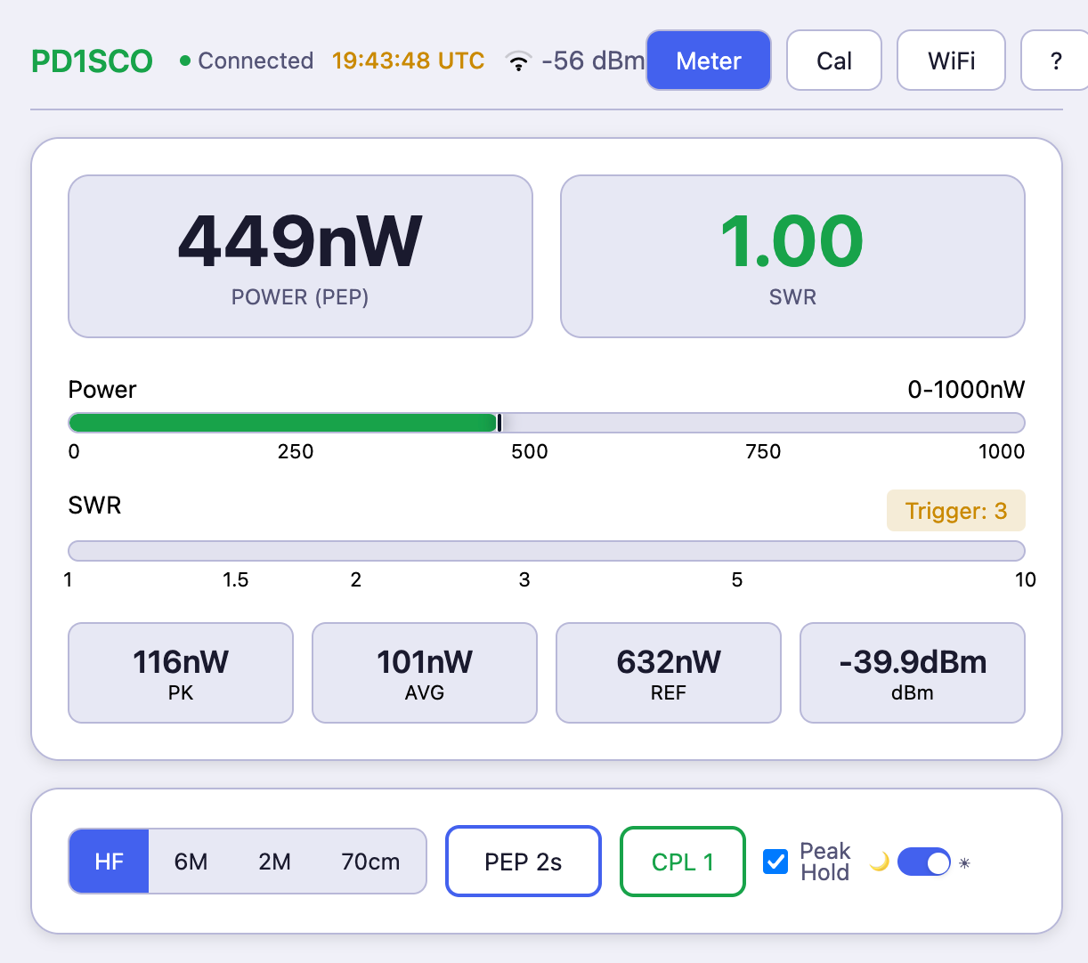
What did this end up costing?
This is a fully open source project, and you need to source the parts yourself. If you do it with a group, costs can be split somewhat. Doing it solo, keep in mind that parts often need to be ordered in batches of 5 or 10. That definitely pushes the cost up, but hey, you might well use the leftovers on a future project…
Below is a list of everything I used. This excludes the coffee tin I built everything into.
| Project | Ref | Part | Qty | Supplier | Part Number | Unit incl. | Sub incl. |
|---|---|---|---|---|---|---|---|
| CPU Coupler | Dual Coupler PCB | 5 | PCB Way | sub includes shipping, handling + taxes | € 5.00 | € 8.19 | |
| HF Coupler | HF Coupler PCB | 10 | PCB Way | sub includes shipping, handling + taxes | € 5.00 | € 8.19 | |
| CPU Coupler | Screen connector PCB | 10 | PCB Way | sub includes shipping, handling + taxes | € 5.00 | € 8.19 | |
| Web Server | ESP32 Breakout PCB | 10 | PCB Way | sub includes shipping, handling + taxes | € 5.00 | € 8.19 | |
| CPU Coupler | R4, R5 | 52.3Ω, 1206, 1% | 2 | Farnell | ERJP08F52R3V | € 0.1585 | € 0.32 |
| CPU Coupler | R7, R8, R11, R12 | 69.8Ω, 1206, 1% | 4 | Farnell | CRCW120669R8FKEA | € 0.0411 | € 0.16 |
| CPU Coupler | R9, R10 | 150Ω, 1206, 1% | 2 | Farnell | WR12X1500FTL | € 0.0109 | € 0.02 |
| CPU Coupler | R13, R14 | 2.2kΩ, 1206 | 2 | Farnell | MCMR12X2201FTL | € 0.0145 | € 0.03 |
| CPU Coupler | C18, C19 | 10pF, 1206, C0G/NP0 | 2 | Farnell | C1206C100J5GACTU | € 0.0774 | € 0.15 |
| CPU Coupler | C15 | 1nF, 1206 | 1 | Farnell | C1206C102J5RACTU | € 0.0883 | € 0.09 |
| CPU Coupler | C5, C6, C13, C25 | 10nF, 1206 | 4 | Farnell | C1206C103J5RACTU | € 0.0544 | € 0.22 |
| CPU Coupler | C1-4, C9-12, C14, C16, C17, C20-23, C26 | 100nF, 1206 | 16 | Farnell | C1206C104J3RECTU | € 0.1174 | € 1.88 |
| CPU Coupler | C24 | 22µF/35V | 1 | Farnell | EEE1VA220SP | € 0.3206 | € 0.32 |
| CPU Coupler | L1-4 | 22nH, 0805, high-Q | 4 | Farnell | CW201212-22NJ | € 0.2311 | € 0.92 |
| CPU Coupler | FB1-4 | 600Ω @ 100MHz, 1206 | 4 | Farnell | MH3261-601Y | € 0.1162 | € 0.46 |
| CPU Coupler | U1, U2 | AD8307, SOIC-8 | 2 | Digikey | AD8307ARZ-REELCT-ND | € 21.5259 | € 43.05 |
| CPU Coupler | U7, U8 | PE4259-63, SPDT RF sw | 2 | Digikey | 1046-1011-1-ND | € 0.8591 | € 1.72 |
| CPU Coupler | U3 | ISL60002DIH326Z | 1 | Farnell | ISL60002DIH326Z-TK | € 2.8798 | € 2.88 |
| CPU Coupler | U4 | AD7991 | 1 | Farnell | AD7991YRJZ-0500RL7 | € 10.8658 | € 10.87 |
| CPU Coupler | U6 | TSR 1-2450 | 1 | Farnell | TSR 1-2450E | € 3.6905 | € 3.69 |
| CPU Coupler | LS1 | PT-1245P-PQ | 1 | Farnell | KXG1205C | € 1.1132 | € 1.11 |
| CPU Coupler | F1 | 500mA/40V, 1812 | 1 | Farnell | 1812L050/30PR | € 0.9390 | € 0.94 |
| CPU Coupler | J4 | 5×2 pin header | 1 | Farnell | 61201021621 | € 0.5469 | € 0.55 |
| CPU Coupler | X1, X3 | U.FL-R-SMT IPX board SMT | 2 | AliExpress | Sold in packs of 10 at € 4.49 | € 0.449 | € 0.90 |
| CPU Coupler | X2, X4 | SMA Connector, right-angle | 2 | AliExpress | € 0.40 | € 0.80 | |
| CPU Coupler | Cable | Connector cable to screen | 1 | AliExpress | 2x5 (10p), sold in packs of 2 | € 1.045 | € 1.05 |
| HF Coupler | R1, R2 | 100Ω, 2W, 2512 | 2 | Farnell | MCHP122WF1000T4E | € 0.2977 | € 0.60 |
| HF Coupler | R3, R4 | 68Ω, 2W, 2512 | 2 | Farnell | MCHP122WF680JT4E | € 0.2662 | € 0.53 |
| HF Coupler | R5, R6 | 100Ω, 0.25W, 1206 | 2 | Farnell | RT1206FRD07100RL | € 0.0351 | € 0.07 |
| HF Coupler | C1, C2 | 15pF, 1206, NP0, 50V | 2 | Farnell | C1206C150J5GACTU | € 0.0569 | € 0.11 |
| HF Coupler | L1-4 | 82nH, 0805, high-Q | 4 | Farnell | 0805HP-82NXGRB | € 1.1011 | € 4.40 |
| HF Coupler | T2 (Large) | Toroid FT83-43 (Fair-rite 5943000501) | 1 | Digikey | 1934-1217-ND (the difference from a regular FT82A-43 is that this one is twice the height.) | € 1.8513 | € 1.85 |
| HF Coupler | T1 (Small) | Toroid FT50-43 | 1 | HFkits | https://www.hfkits.nl/product/amidon-ft50-43-ferriet-ringkern/ | € 0.60 | € 0.60 |
| HF Coupler | Coax | RG-142 *1 | 1 | AliExpress | € 2.26 | ||
| HF Coupler | Coax | RG-213 *2 | 1 | PA1HJT | Donated by a generous fellow amateur | € -,– | |
| HF Coupler | Wire | 22 AWG heat-strippable (155°C) | ± 50-55cm | AliExpress | Needed for winding the FT50-43. 0.6mm enameled copper wire. | € -,– | |
| HF Coupler | Wire | 18 AWG heat-strippable (155°C) | ± 90 cm | AliExpress | Needed for winding the FT83-43. 1mm enameled copper wire. | € -,– | |
| HF Coupler | SO-239 | SO-239 panel mount connector | 2 | AliExpress | € 1.94 | € 3.88 | |
| HF Coupler | SMA | SMA female mount connector | 2 | AliExpress | Sold in packs of 4 at € 2.88 | € 0.72 | € 1.44 |
| HF Coupler | Case | Hammond 1590BS clone | 1 | AliExpress | € 4.95 | € 4.95 | |
| COMPUTE | Teensy 4.0 | 1 | TinyTronics | € 26.25 | € 26.25 | ||
| COMPUTE | ESP32-C3 | 1 | TinyTronics | € 6.50 | € 6.50 | ||
| SCREEN | BuyDisplay.com | 1 | BuyDisplay.com | The screen is very picky about matching exactly. Please don’t deviate from the URL below to avoid problems!! https://www.buydisplay.com/5-inch-tft-lcd-display-capacitive-touchscreen-ra8875-controller-800x480 be sure to also order these sub-components:
|
€ 40.80 | € 54.10 | |
| Total | € 211.24 |
- *1 = Coax from AliExpress can get pricey. The cheapest option was a connector cable that I just cut apart.
- *2 = I didn’t have any RG-213 myself, but a 10mm-thick coax works just fine.
So, what’s next?!
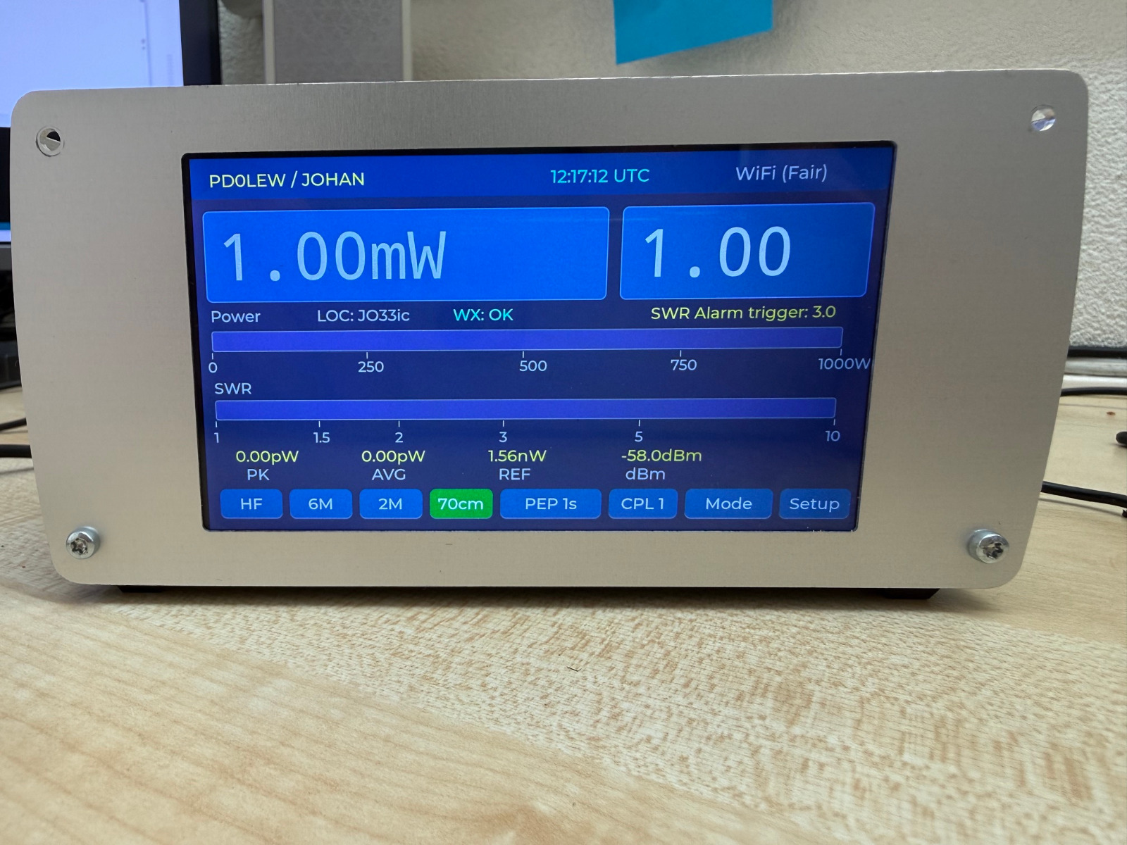
New screen concept
As mentioned, the project is very much alive, and new developments keep coming. The latest nice step, since the start of my own adventure, is a brand new screen based on an ESP32-P4-WiFi6-Touch-LCD-5. This picture is a recent development from Johan, which he shared with me to include in this article. A gorgeous new screen: very bright, and opening up new possibilities for the future.
For now, I’m going to enjoy the meter I already have — but I’m not ruling out doing the conversion to the new screen at some point down the line. What a fantastic piece of kit. And that, to me, is the best thing about an open source project: a nice new addition like this opens the door to new DIY projects and expansions for the future.